MEDVIC 연구실
MEchanical Design and VIbration Control
Research
- HOME
- Research
- Seal
Seal
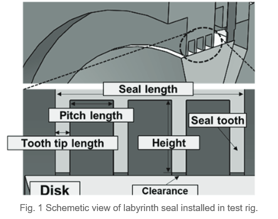
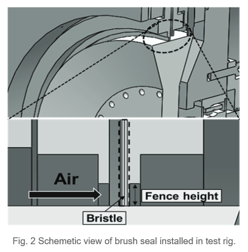
Seals play a role in reducing and controlling leakage flows in a gap between rotating and stationary parts, thus improving energy effciency in various fluid machinery such as gas turbines, steam turbines, turbocompressors, and turbopumps. In general, there are two types of seals: contact seal and non-contact seal for rotating machinery. The contact seal has the advantage of low leakage, but there is a risk of damage to parts due to friction caused by the contact between the rotor and the stator. In the case of the non-contact seal, damage to parts does not occur because there is no friction, but there is a concern that a large amount of leakage may occur. A hybrid seal uses both the advantages of the non-contact and contact seals by using hydrostatic pressure and hydrodynamic pressure effects to form a small gas film between the rotor and stator. Fig. 1,2,3 shows schemetic view of labyrinth seal installed in test rig.


Fig. 4 shows the overall photograph and schematic diagram of the rotating test rig for dynamic seal experiments. The experimental setup mainly consists of an inlet/outlet pressure control system, a flowmeter, and the rotating test rig. The inlet pressure and pressure ratio can be adjusted using the pressure control system, and a flowmeter installed between the test rig inlet and the inlet pressure control system measures the leakage flow rate of air. In the rotating test rig, displacement sensors are installed at the 12 o'clock and 3 o'clock positions relative to the inlet direction to monitor the rotor orbit in real-time, ensuring the stability of the rotating system. pressure sensors are installed at the inlet and outlet of the seal in the test rig to measure the pressure. The rotational speed of the rotor is measured using a tachometer.

Fig. 5 presents a graph comparing the leakage flow rates of three types of seals (Labyrinth seal, Brush seal, and hydrid hydrodynamic seal) under an inlet pressure of 2.6 bar A and a rotational speed of 10,000 rpm, with varying pressure ratios. The leakage flow rates are nondimensionalized using the leakage flow rate of the Labyrinth seal at the maximum pressure ratio as the reference. The leakage flow rate is largest for the Labyrinth seal, followed by the Brush seal and the hybrid hydrodynamic seal. The Labyrinth seal exhibits a leakage flow rate approximately twice that of the Brush seal. Notably, the hybrid hydrodynamic seal sows a smaller increase in leakage flow rate with increasing pressure ratio compared to the other two seals. This indicates that the hybrid hydrodynamic seal is less sensitive to sudden changes in pressure, demonstrating greater stability in leakage performance under varying pressure conditions.

